Logic AND Gate Tutorial

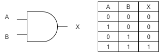
The Logic AND Gate is a type of digital logic circuit whose output goes HIGH to a logic level 1 only when all of its inputs are HIGH
The output state of a digital logic AND gate only returns “LOW” again when ANY of its inputs are at a logic level “0”. In other words for a logic AND gate, any LOW input will give a LOW output.
The logic or Boolean expression given for a digital AND gate is that for Logical Multiplication which is denoted by a single dot or full stop symbol, ( . ) giving us the Boolean expression of: A.B = Q.
Then we can define the operation of a digital 2-input AND gate as being:
“If both A and B are true, then Q is true”
2-input Transistor AND Gate
A simple 2-input AND gate can be constructed using RTL Resistor-transistor switches connected together as shown below with the inputs connected directly to the transistor bases. Both transistors must be saturated “ON” for an output at Q.

Logic AND Gates are available using digital circuits to produce the desired logical function and is given a symbol whose shape represents the logical operation of the AND gate.
Digital AND Gate Types
The 2-input Logic AND Gate
| Symbol | Truth Table | ||

2-input AND Gate
|
B | A | Q |
| 0 | 0 | 0 | |
| 0 | 1 | 0 | |
| 1 | 0 | 0 | |
| 1 | 1 | 1 | |
| Boolean Expression Q = A.B | Read as A AND B gives Q | ||
The 3-input Logic AND Gate
| Symbol | Truth Table | |||

3-input AND Gate
|
C | B | A | Q |
| 0 | 0 | 0 | 0 | |
| 0 | 0 | 1 | 0 | |
| 0 | 1 | 0 | 0 | |
| 0 | 1 | 1 | 0 | |
| 1 | 0 | 0 | 0 | |
| 1 | 0 | 1 | 0 | |
| 1 | 1 | 0 | 0 | |
| 1 | 1 | 1 | 1 | |
| Boolean Expression Q = A.B.C | Read as A AND B AND C gives Q | |||
Because the Boolean expression for the AND function is defined as (.), which is a binary operation, AND gates can be cascaded together to form any number of individual inputs. However, commercial available AND gate IC’s are only available in standard 2, 3, or 4-input packages. If additional inputs are required, then standard AND gates will need to be cascaded together to obtain the required input value, for example.
Multi-input AND Gate

The Boolean Expression for this 6-input AND gate will therefore be:
Q = (A.B).(C.D).(E.F)
In other words:
A AND B AND C AND D AND E AND F gives Q
If the number of inputs required is an odd number of inputs any “unused” inputs can be held HIGH by connecting them directly to the power supply using suitable “Pull-up”